
Space segment
Structure + Mechanism
The outer structure consists of four rails and four sidewalls made out of an aluminum alloy. For weight reduction some cut outs in the sidewalls exist. The inner structure consists of several panels hold in place by standoffs. The height of the standoffs can be adjusted to match the needs of each mounted subsystem.
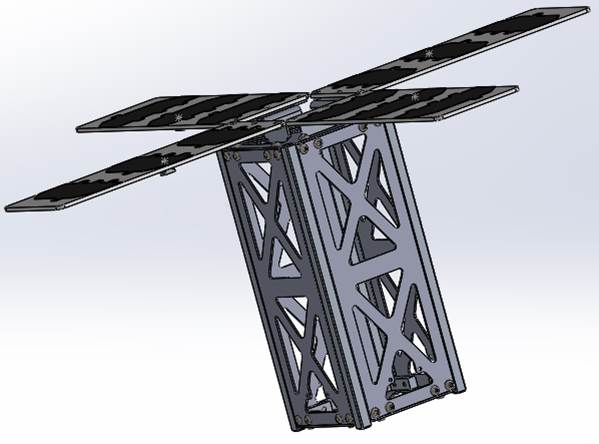
Body mounted solar arrays cannot supply sufficient power for the cubesat. To overcome this issue a solar array deploy mechanism (SADM) including a hold-down and release mechanism has been developed. The SADM is driven by two preloaded springs. As soon as the panels reach the destination position an end position catch fixates the panels. The SADM increases the effective surface facing the sun from 2U to 8U.
Power Control and Distribution Unit
The power concept of the satellite is set to have no power reconditioning on subsystem level. All required voltages are to be regulated by the central power control and distribution unit (PCDU). The primary side of the PCDU is connected to a maximum power point tracker regulating the output of the solar arrays. Within the PCDU a battery controller is managing the charge and discharging of the battery. The battery maximum capacity is set to be 20Wh at 12V.
On its secondary side the PCDU supplies the voltages 12V, 5V and 3.3 V as regulated power lines. For the voltage conversion a combination of up- and down converters is used. Each power outlet is individually supervised by a latching current limiter (LCL) with regards to the voltage and flowing current. In case of over current, under voltage or over voltage beyond a specified time the LCL disconnects the subsystem from the power supply. The LCLs are partitioned for each connected subsystem.
The PCDU reports internal housekeeping data upon request to the On-Board computer (OBC) and reacts to commands sent by the OBC. The PCDU is an in-house development by students of the DHBW.
Datalink
The design of the datalink consists of two separate links. One is for the commanding and transmission of housekeeping data, the other for downlinking the payload data. The mission aims to downlink seven pictures a day from the payload. The payload link requires a very high rated chanal capacity. For the TM/TC Datenlink a Cross-lamenda/2 dipol shall serve.
For the downlink of the payload data an S-Band link with a patch array antenna on the space segment is foreseen. With a to be developed 2×2 patch antenna array again of almost 12dBi can be reached, which is 4dB more compared to other commercially available single S-Band patch antennas. 2×2 patch antennas for CubeSats are so far only available in X-Band.
The ground station for the UHF Link already existis at the DHBW Ravensburg Campus Friedrichshafen. The available station is registered under the call sign DK0TE and fully supports satellite tracking and doppler correction. Communication with other cubesats happens on a regular basis.
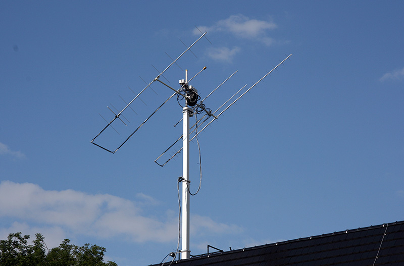
For the S-Band ground stations a concept of a network of ground stations around the globe is foreseen. The project is talking to different potential service provider and partners. As an alternative the upgrade of the station in Friedrichshafen to support the S- band link is analyzed. A static down link budget of -122dBm for the S- Band and -121dBm for the UHF-Link was calculated.
Attitude determination and control system
The attitude determination and control system (ADCS), is responsible for acquiring position and attitude information through different sensors and controlling the attitude using actuators. The ADCS has to operate in different modes. The tasks of the ADCS range from detumbling after separation from the launcher to pointing to a point of interest on the earth. A pointing accuracy of the satellite better than one degree is required to allow proper operation of the imager. Furthermore the ADCS needs to ensure that none of the optics is facing the sun during the complete lifetime of the satellite.
The attitude information will be gathered by magnetometers, gyroscopes along all three axis and a miniature star tracker. For determination of the position a global navigation satellite system (GNSS) receiver will be on board. The satellite’s attitude shall be controlled using magnetorquers and small reactions wheels along all three axis of the satellite. As a passive contribution of stabilizing the satellite the gravitation gradient shall be used. Therefore the moment of inertia will be trimmed by arranging the subsystems accordingly. The satellite will align itself with the axis of the minimal moment pointing towards the earth surface without any of the actuators active.
On Board Software Architecture
In opposite to common satellite software development, the SeeSat will follow an untypical approach of higher abstraction. This is based on the state-of-the-art software architectural principle found in common software products. To achieve the abstraction along with a commercial of the shelf (COTS) realtime operating system (RTOS), like µC/OS, two layers are going to be implemented to enhance portability. The first layer will abstract the real time operating system, running on the onboard computer. This Operating System Abstraction Layer (OSAL) is topped by the second layer, which will decouple the application software. The communication within the software system will be message based, handled by the middleware. This software framework is already defined in terms of the middleware’s API. As a reference for the middleware the standard for avionics application software ARINC 653 was used.